Thursday, July 31, 2008

how does airplane rotate


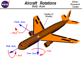
Since we live in a three dimensional world, it is necessary to control the attitude or orientation of a flying aircraft in all three dimensions. In flight, any aircraft will rotate about its center of gravity, a point which is the average location of the mass of the aircraft. We can define a three dimensional coordinate system through the center of gravity with each axis of this coordinate system perpendicular to the other two axes. We can then define the orientation of the aircraft by the amount of rotation of the parts of the aircraft along these principal axes.

The yaw axis is defined to be perpendicular to the plane of the wings with its origin at the center of gravity and directed towards the bottom of the aircraft. A yaw motion is a movement of the nose of the aircraft from side to side. The pitch axis is perpendicular to the yaw axis and is parallel to the plane of the wings with its origin at the center of gravity and directed towards the right wing tip. A pitch motion is an up or down movement of the nose of the aircraft. The roll axis is perpendicular to the other two axes with its origin at the center of gravity, and is directed towards the nose of the aircraft. A rolling motion is an up and down movement of the wing tips of the aircraft.

In flight, the control surfaces of an aircraft produce aerodynamic forces. These forces are applied at the center of pressure of the control surfaces which are some distance from the aircraft cg and produce torques (or moments) about the principal axes. The torques cause the aircraft to rotate. The elevators produce a pitching moment, the rudder produces a yawing moment, and the ailerons produce a rolling moment. The ability to vary the amount of the force and the moment allows the pilot to maneuver or to trim the aircraft. The first aircraft to demonstrate active control about all three axes was the Wright brothers' 1902 glider.

what is center of gravity


An airplane in flight can be maneuvered by the pilot using the aerodynamic control surfaces; the elevator, rudder, or ailerons. As the control surfaces change the amount of force that each surface generates, the aircraft rotates about a point called the center of gravity. The center of gravity is the average location of the weight of the aircraft. The weight is actually distributed throughout the airplane, and for some problems it is important to know the distribution. But for total aircraft maneuvering, we need to be concerned with only the total weight and the location of the center of gravity.


How do engineers determine the location of the center of gravity for an airplane which they are designing?


An airplane is a combination of many parts; the wings, engines, fuselage, and tail, plus the payload and the fuel. Each part has a weight associated with it which the engineer can estimate, or calculate, using Newton's weight equation:


w = m * g


where w is the weight, m is the mass, and g is the gravitational constant which is 32.2 ft/square sec in English units and 9.8 meters/square sec in metric units. To determine the center of gravity cg, we choose a reference location, or reference line. The cg is determined relative to this reference location. The total weight of the aircraft is simply the sum of all the individual weights of the components. Since the center of gravity is an average location of the weight, we can say that the weight of the entire aircraft W times the location cg of the center of gravity is equal to the sum of the weight w of each component times the distance d of that component from the reference location:


W * cg = [w * d](fuselage) + [w * d](wing) + [w * d](engines) + ...


The center of gravity is the mass-weighted average of the component locations.
We can generalize the technique discussed above. If we had a total of "n" discrete components, the center of gravity cg of the aircraft times the weight W of the aircraft would be the sum of the individual i component weight times the distance d from the reference line (w * d) with the index i going from 1 to n. Mathematicians use the greek letter sigma to denote this addition. (Sigma is a zig-zag symbol with the index designation being placed below the bottom bar, the total number of additions placed over the top bar, and the variable to be summed placed to the right of the sigma with each component designated by the index.)


W * cg = SUM(i=1 to i=n) [w * d]i


This equation says that the center of gravity times the sum of "n" parts' weight is equal to the sum of "n" parts' weight times their distance. The discrete equation works for "n" discrete parts.


Source: nasa
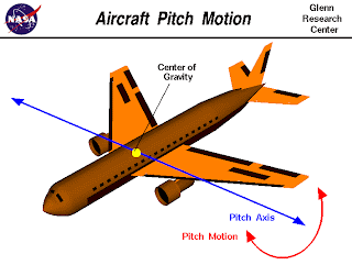
airplane pitch motion


In flight, any aircraft will rotate about its center of gravity, a point which is the average location of the mass of the aircraft. We can define a three dimensional coordinate system through the center of gravity with each axis of this coordinate system perpendicular to the other two axes. We can then define the orientation of the aircraft by the amount of rotation of the parts of the aircraft along these principal axes. The pitch axis is perpendicular to the aircraft centerline and lies in the plane of the wings. A pitch motion is an up or down movement of the nose of the aircraft as shown in the animation.
The pitching motion is being caused by the deflection of the elevator of this aircraft. The elevator is a hinged section at the rear of the horizontal stabilizer. There is usually an elevator on each side of the vertical stabilizer. The elevators work in pairs; when the right elevator goes up, the left elevator also goes up.
As described on the shape effects slide, changing the angle of deflection at the rear of an airfoil changes the amount of lift generated by the foil. With greater downward deflection, lift increases in the upward direction. With greater upward deflection, lift increases in the downward direction. The lift generated by the elevator acts through the center of pressure of the elevator and horizontal stabilizer and is located at some distance from the center of gravity of the aircraft. The change in lift created by deflecting the elevator generates a torque about the center of gravity which causes the airplane to rotate. The pilot can use this ability to make the airplane loop. Or, since many aircraft loop naturally, the deflection can be used to trim or balance the aircraft, thus preventing a loop.


On many aircraft, the horizontal stabilizer and elevator create a symmetric airfoil like the one shown on the left of the shape effects slide. This produces no lift when the elevator is aligned with the stabilizer and allows the combination to produce either positive or negative lift, depending on the deflection of the elevator. On many fighter planes, in order to meet their high maneuvering requirements, the stabilizer and elevator are combined into one large moving surface called a stabilator. The change in force is created by changing the inclination of the entire surface, not by changing its effective shape.

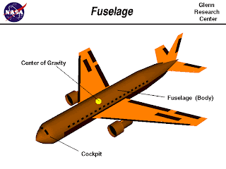
What is fuselage


Airplanes are transportation devices which are designed to move people and cargo from one place to another. Airplanes come in many different shapes and sizes depending on the mission of the aircraft. The airplane shown on this slide is a turbine-powered airliner which has been chosen as a representative aircraft.

The fuselage, or body of the airplane, is a long hollow tube which holds all the pieces of an airplane together. The fuselage is hollow to reduce weight. As with most other parts of the airplane, the shape of the fuselage is normally determined by the mission of the aircraft. A supersonic fighter plane has a very slender, streamlined fuselage to reduce the drag associated with high speed flight. An airliner has a wider fuselage to carry the maximum number of passengers. On an airliner, the pilots sit in a cockpit at the front of the fuselage. Passengers and cargo are carried in the rear of the fuselage and the fuel is usually stored in the wings. For a fighter plane, the cockpit is normally on top of the fuselage, weapons are carried on the wings, and the engines and fuel are placed at the rear of the fuselage.

The weight of an aircraft is distributed all along the aircraft. The fuselage, along with the passengers and cargo, contribute a significant portion of the weight of an aircraft. The center of gravity of the aircraft is the average location of the weight and it is usually located inside the fuselage. In flight, the aircraft rotates around the center of gravity because of torques generated by the elevator, rudder, and ailerons. The fuselage must be designed with enough strength to withstand these torques.
Source: nasa

how do airplane up and down


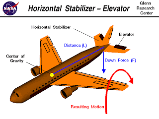
At the rear of the fuselage of most aircraft one finds a horizontal stabilizer and an elevator. The stabilizer is a fixed wing section whose job is to provide stability for the aircraft, to keep it flying straight. The horizontal stabilizer prevents up-and-down, or pitching, motion of the aircraft nose. The elevator is the small moving section at the rear of the stabilizer that is attached to the fixed sections by hinges. Because the elevator moves, it varies the amount of force generated by the tail surface and is used to generate and control the pitching motion of the aircraft. There is an elevator attached to each side of the fuselage. The elevators work in pairs; when the right elevator goes up, the left elevator also goes up. This slide shows what happens when the pilot deflects the elevator.


The elevator is used to control the position of the nose of the aircraft and the angle of attack of the wing. Changing the inclination of the wing to the local flight path changes the amount of lift which the wing generates. This, in turn, causes the aircraft to climb or dive. During take off the elevators are used to bring the nose of the aircraft up to begin the climb out. During a banked turn, elevator inputs can increase the lift and cause a tighter turn. That is why elevator performance is so important for fighter aircraft.


The elevators work by changing the effective shape of the airfoil of the horizontal stabilizer. As described on the shape effects slide, changing the angle of deflection at the rear of an airfoil changes the amount of lift generated by the foil. With greater downward deflection of the trailing edge, lift increases. With greater upward deflection of the trailing edge, lift decreases and can even become negative as shown on this slide. The lift force (F) is applied at center of pressure of the horizontal stabilzer which is some distance (L) from the aircraft center of gravity. This creates a torque


T = F * L


on the aircraft and the aircraft rotates about its center of gravity. The pilot can use this ability to make the airplane loop. Or, since many aircraft loop naturally, the deflection can be used to trim or balance the aircraft, thus preventing a loop. If the pilot reverses the elevator deflection to down, the aircraft pitches in the opposite direction


Source: nasa

How do the Ailerons work


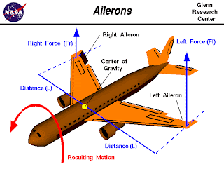
Ailerons can be used to generate a rolling motion for an aircraft. Ailerons are small hinged sections on the outboard portion of a wing. Ailerons usually work in opposition: as the right aileron is deflected upward, the left is deflected downward, and vice versa. This slide shows what happens when the pilot deflects the right aileron upwards and the left aileron downwards.
The ailerons are used to bank the aircraft; to cause one wing tip to move up and the other wing tip to move down. The banking creates an unbalanced side force component of the large wing lift force which causes the aircraft's flight path to curve. (Airplanes turn because of banking created by the ailerons, not because of a rudder input

.
The ailerons work by changing the effective shape of the airfoil of the outer portion of the wing. As described on the shape effects slide, changing the angle of deflection at the rear of an airfoil will change the amount of lift generated by the foil. With greater downward deflection, the lift will increase in the upward direction. Notice on this slide that the aileron on the left wing, as viewed from the rear of the aircraft, is deflected down. The aileron on the right wing is deflected up. Therefore, the lift on the left wing is increased, while the lift on the right wing is decreased. For both wings, the lift force (Fr or Fl) of the wing section through the aileron is applied at the aerodynamic center of the section which is some distance (L) from the aircraft center of gravity. This creates a torque


T = F * L


about the center of gravity. If the forces (and distances) are equal there is no net torque on the aircraft. But if the forces are unequal, there is a net torque and the aircraft rotates about its center of gravity. For the conditions shown in the figure, the resulting motion will roll the aircraft to the right (clockwise) as viewed from the rear. If the pilot reverses the aileron deflections (right aileron down, left aileron up) the aircraft will roll in the opposite direction. We have chosen to name the left wing and right wing based on a view from the back of the aircraft towards the nose, because that is the direction in which the pilot is looking.

Source: nasa

how does the rudder work


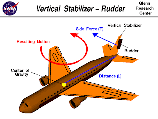
At the rear of the fuselage of most aircraft one finds a vertical stabilizer and a rudder. The stabilizer is a fixed wing section whose job is to provide stability for the aircraft, to keep it flying straight. The vertical stabilizer prevents side-to-side, or yawing, motion of the aircraft nose. The rudder is the small moving section at the rear of the stabilizer that is attached to the fixed sections by hinges. Because the rudder moves, it varies the amount of force generated by the tail surface and is used to generate and control the yawing motion of the aircraft. This slide shows what happens when the pilot deflects the rudder, a hinged section at the rear of the vertical stabilizer.


The rudder is used to control the position of the nose of the aircraft. Interestingly, it is NOT used to turn the aircraft in flight. Aircraft turns are caused by banking the aircraft to one side using either ailerons or spoilers. The banking creates an unbalanced side force component of the large wing lift force which causes the aircraft's flight path to curve. The rudder input insures that the aircraft is properly aligned to the curved flight path during the maneuver. Otherwise, the aircraft would encounter additional drag or even a possible adverse yaw condition in which, due to increased drag from the control surfaces, the nose would move farther off the flight path.
The rudder works by changing the effective shape of the airfoil of the vertical stabilizer. As described on the shape effects slide, changing the angle of deflection at the rear of an airfoil will change the amount of lift generated by the foil. With increased deflection, the lift will increase in the opposite direction. The rudder and vertical stabilizer are mounted so that they will produce forces from side to side, not up and down. The side force (F) is applied through the center of pressure of the vertical stabilizer which is some distance (L) from the aircraft center of gravity. This creates a torque

T = F * L

on the aircraft and the aircraft rotates about its center of gravity. With greater rudder deflection to the left as viewed from the back of the aircraft, the force increases to the right. If the pilot reverses the rudder deflection to the right, the aircraft will yaw in the opposite direction. We have chosen to base the deflections on a view from the back of the aircraft towards the nose, because that is the direction in which the pilot is looking
Source: nasa